DWG Export Options
- Matt Siebert
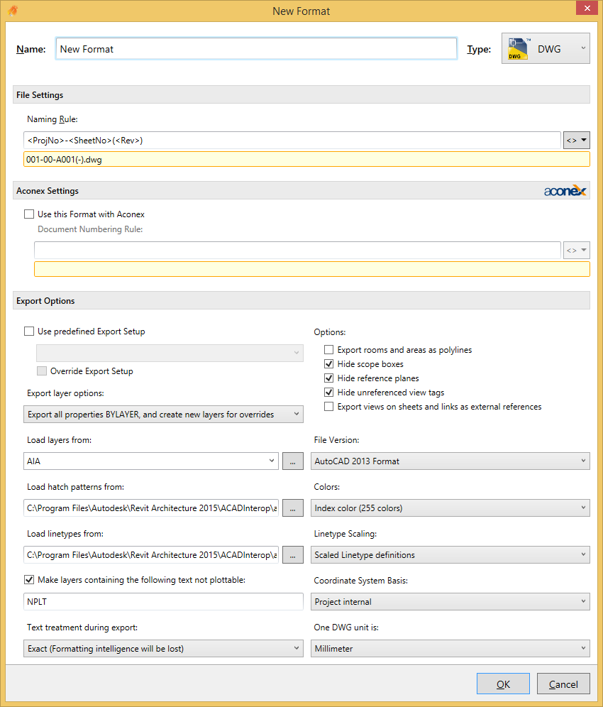
File Settings
Naming Rule
The Naming Rule setting defines a rule that will be used to name the exported file. See Naming Rules and Output Locations for more information.
Aconex Settings
See the Format dialog section for more information.
Export Options
Use Pre-defined Export Setup
Check this option if you would like to use one of the predefined export setups from the DWG/DXF Export Setups settings in Revit. This option is provided as not all options available in this dialog are accessible through the API directly. You can choose to use an Export Setup and by ticking the “Override Export Setup” you can override particular settings from this setup with options in Xrev Transmit.
Export Layer Options
Select one of the following Export layer options to specify how Revit elements with view-specific graphic overrides will be mapped to CAD layers. (Graphic properties of Revit elements, such as colour, line weight, and line style, are defined in the Object Styles of the categories to which the elements belong, but these definitions can be overridden for a selected element in a specific view.)
Export category properties BYLAYER and overrides BYENTITY - A Revit element with view-specific graphic overrides will retain those overrides in the CAD application, but will reside on the same CAD layer as other entities in the same Revit category.
Export all properties BYLAYER, but do not export overrides - View-specific graphic overrides will be ignored in the CAD application. Any exported Revit element will reside on the same CAD layer as other entities in the same Revit category. By forcing all entities to display the visual properties defined by their layer, this option results in a lower number of layers and provides by-layer control over the exported DWG/DWF file.
Export all properties BYLAYER, and create new layers for overrides - A Revit element with view-specific graphics will be placed on its own CAD layer. This option provides by-layer control over the exported DGN file, and preserves graphical intent. However, it increases the number of layers in the exported DGN file.
Load layers from
Specify the layer mapping file to be used, either by selecting one of the standards from the drop down or using the browse button to select your own.
Load Hatch Patterns
Specify a hatch pattern (.pat file) that is used in the file mapping table in the standard Revit Exports. Note the mapping table is not accessible through the Revit API and as such is unable to be provided as an option here.
Load linetypes from
Specify a linetypes file (.lin) that is used in the file mapping table in the standard Revit Exports. Note the mapping table is not accessible through the Revit API and as such is unable to be provided as an option here.
Make Layers containing the following text not plottable
Any layers that can contain NPLT as defined in the Export Layers file will automatically be set as non-plottable.
Text Treatment during Export
From this drop-down list, select one of the following options:
Exact (Formatting intelligence will be lost) - Exported text will look exactly as it does in Revit (exact line wrapping). However, if the text includes bulleted or numbered lists, that paragraph functionality is lost upon export. Pressing Enter within a formatted paragraph will not restore the formatting.
Approximate (Formatting intelligence will be maintained) - If exported text includes bulleted or numbered lists, that paragraph functionality is maintained when the text is edited. Pressing Enter within a formatted paragraph will restore the formatting. However, the visual appearance of the text may vary from the original, whether or not the note contains a list (that is, wrapping may vary).
Options
Export rooms and areas as polylines
Select the Export rooms and areas as polylines option if you want rooms and areas to be exported to a DWG file as closed polylines.
Area polylines are generated from area plan views only.
Room polylines are generated from floor plan views or ceiling plan views only.
Hide scope boxes
Automatically turn off any visible scope boxes so they don’t print/export
Hide reference planes
Automatically turn off reference planes so they don’t print/export
Hide unreferenced view tags
Automatically turn off any sections/elevations/callouts that have not been placed on sheets yet
Export Views on Sheets and Links as External References
Specify whether each view on the sheet will be exported as an individual file and Xref’d to the sheet file or as a single file.
Note: There are no naming controls for the Xref’d views currently available in Xrev Transmit or through the Revit API.
File Version
Select which version of AutoCAD you wish to export the DWG to.
Colors
Select either of the following options to specify how colors are exported:
Index color (255 Colors) - For colors that are set by category, the indexed colors will be used. When colors are not set by category and the override is preserved in the export, Revit uses the closest match from the 255 indexed colors and thus may not provide an exact match for RGB and Pantone® colors.
True colour (RGB Values) - This uses the RGB value from Revit for the ByLayer and ByEntity parameters. For example, when you export room (or space) colour fills, the colours in the exported file will exactly match those in the original file.
Linetype Scaling
In AutoCAD, the PSLTSCALE parameter controls paper space linetype scaling. A value of 0 indicates no special linetype scaling. Linetype dash lengths are based on the drawing units of the space (model or paper) in which the objects were created. A value of 1 indicates that viewport scaling governs linetype scaling.
In Revit, the Linetype Scaling setting changes the default behaviour of the exported DWG files. Some lines that you would expect to be dashed may now appear solid or in a different scale in either Model or Sheet View in AutoCAD. Regardless of the option you choose, the DWG linetype definitions are created so that a dashed line always begins and ends with a dash.
You can select any of the following options to control the LTSCALE and PSLTSCALE settings in AutoCAD and to control how linetype definitions are exported from Revit:
Scaled Linetype definitions - This option preserves graphical intent by exporting linetypes the same as they were previously scaled by view scale.
Modelspace (PSLTSCALE = 0) - This option sets the LTSCALE parameter to view scale and the PSLTSCALE to 0.
Paperspace (PSLTSCALE = 1) - This option sets the value of both LTSCALE and PSLTSCALE to 1. Revit linetype definitions are scaled to reflect project units, but otherwise they are exported as is.
Coordinate System Basis
Select where you want to export with the Project Internal coordinates or the shared coordinates.
Note: The Shared Coordinates setting has no affect when exporting Sheets.
One DWG unit is
Specify the exported DWG unit system.